Screw Air Compressor High-Temperature Alarm: Causes and Troubleshooting
When a screw compressor reports a high discharge temperature or a high air-end outlet temperature, inspect ventilation, coolers, lubricant, cooling fan, cooling-water circuit, thermostatic valve and temperature sensor in a controlled sequence instead of repeatedly resetting the alarm.
· BOSAN
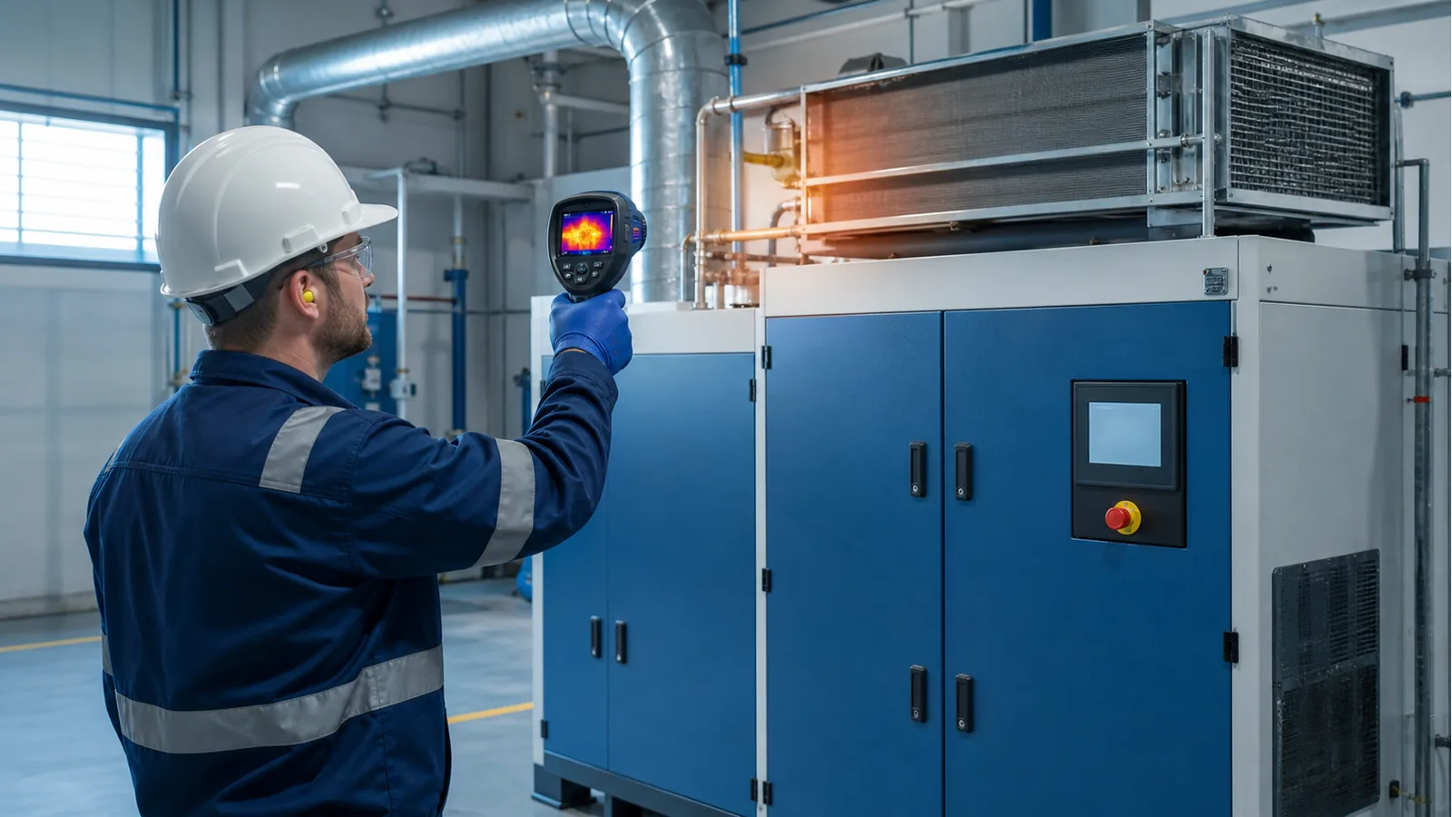
A high-temperature alarm normally means that compression heat is not being removed efficiently, or that the lubricant circuit, cooling system or compressor-room conditions are abnormal. Alarm limits vary by model, lubricant and controller settings. Use the instruction manual and the machine's historical normal readings; do not simply clear the alarm and continue running.
Typical Symptoms
- The controller reports high discharge temperature, air-end outlet temperature or oil temperature and shuts the compressor down.
- Temperature continues to rise after loading, falls slowly after unloading, or alarms occur repeatedly in hot weather or at full load.
- The compressor room is excessively hot and cooler discharge air is being drawn back into the intake.
- The lubricant is dark or smells burnt, or the cooling fan or cooling-water system is not operating normally.
Diagnostic Sequence
- Record the alarm time, ambient temperature, loaded pressure, motor current and temperature trend before shutdown. Determine whether the event is a sustained rise or an implausible sensor jump.
- After shutdown, isolation, depressurization and confirmation that separator-vessel pressure is zero, check the lubricant level exactly as specified in the manual. Low level reduces lubrication and heat removal; excessive level can cause foaming and separation problems.
- Inspect room air inlets, exhaust openings, ductwork and baffles. Confirm that hot discharge air cannot recirculate to the compressor intake.
- Inspect intake filter mats, the air inlet filter and the external cooler surfaces for restriction. Protect electrical components during cleaning and do not force debris deeper into the cooler core.
- Confirm cooling-fan direction, speed and control logic. Check the fan contactor, belt or variable-speed drive where applicable.
- On water-cooled units, verify cooling-water inlet temperature, flow, differential pressure and quality. Confirm that valves are open, strainers are clear and the heat exchanger is not scaled.
- If ventilation, lubricant level and external cleaning are satisfactory, a qualified technician should check the oil filter, internal oil-cooler restriction, thermostatic valve, oil-stop valve, lubricant circuit leakage and temperature-sensor accuracy.
Corrective Actions
- Restore effective room ventilation and separate hot exhaust from intake air; redesign ducting if the installed heat-rejection capacity is inadequate.
- Use the specified lubricant and correct the level using the approved procedure. Oxidized, emulsified or mixed lubricant may require replacement and system cleaning.
- Clean or replace restricted filters and coolers. Restore specified water temperature and flow on water-cooled packages.
- After repairing the fan, thermostatic valve, lubricant circuit or sensor, verify stable temperatures in both unloaded and loaded operation before returning the machine to continuous service.
Stop the Compressor and Call a Qualified Technician When
- The alarm returns shortly after restart or temperature rises rapidly without stabilizing.
- There is a burnt smell, smoke, metallic rubbing, heavy lubricant leakage or carbonized lubricant.
- The air end is difficult to rotate, the cooling fan is stationary, cooling-water flow is absent, or sensor accuracy cannot be confirmed.
Prevention
- Log ambient temperature, discharge temperature and loaded pressure daily to establish a normal baseline.
- Shorten inspection intervals for filter mats, coolers and filter elements in dusty or high-temperature environments.
- Keep compressor-room intake and exhaust paths separated and keep the cooler discharge area clear.
- Service lubricant, the oil filter and thermostatic system according to operating hours and actual lubricant condition.
Important Note
Alarm limits, lubricant-level procedures, lubricant specifications and fan control differ by manufacturer and model. This article identifies diagnostic directions and does not replace the model-specific operating and maintenance manual.