Air Compressor High/Low Voltage or Phase Fault: Safe Troubleshooting Guide
For high-voltage, undervoltage, phase-loss, phase-sequence or DC-bus overvoltage alarms, a qualified electrician must check incoming voltage, phase imbalance, connections, transformer or generator regulation and the drive. Never bypass protection or raise alarm limits to force operation.
· BOSAN
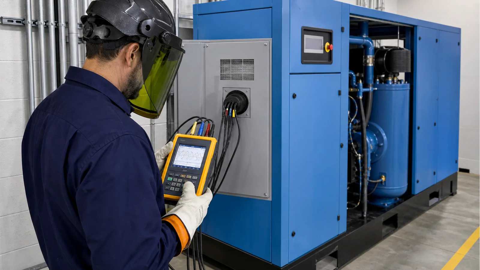
A controller message stating high voltage does not always mean sustained utility overvoltage. On VSD compressors it may indicate DC-bus overvoltage caused by regenerative deceleration, a braking-unit problem or incorrect drive parameters. First identify whether the alarm originates at the incoming supply, control supply, main motor or inside the drive, then evaluate it against the nameplate and model-specific manual.
Typical Symptoms
- The controller reports overvoltage, undervoltage, phase loss, incorrect phase sequence, phase imbalance or drive DC-bus overvoltage.
- The compressor trips during starting, alarms only after loading, or fails mainly on generator power or during lightly loaded utility periods.
- Contactors chatter, the controller reboots, the drive stops, or the three phase currents differ significantly.
- The motor overheats or hums, rotation is incorrect, or fuses and circuit breakers operate repeatedly.
Diagnostic Sequence
- Record the complete alarm code, operating state and time. Identify whether the source is the compressor controller or the variable-speed drive.
- Compare the compressor, motor and drive nameplates with the site's rated voltage and frequency. Confirm that the ordered electrical configuration matches the supply.
- A licensed electrician should measure all three line-to-line voltages under unloaded and loaded conditions and compare them with the controller reading. Check phase imbalance, transient dips and surges. Use the model manual for allowable limits.
- After isolation and verification of zero voltage, inspect incoming terminals, breaker, fuses, contactors and cables for looseness, heat damage, oxidation or inadequate conductor size.
- For transformer or generator supplies, check transformer tap position, generator AVR regulation, capacity and dynamic response. Observe voltage during compressor starting, loading and unloading.
- For drive DC-bus overvoltage, check incoming voltage and have a drive-qualified technician verify deceleration time, speed-control settings, braking resistor or braking unit and motor data.
- Inspect the phase-sequence relay, control transformer and voltage-sensing circuit. If measured voltage is normal but the display is not, calibrate or repair the sensing circuit instead of changing protection limits.
Corrective Actions
- If site voltage is outside the machine's permitted range, keep the compressor stopped and have the utility, electrician or generator service provider correct the supply.
- Tighten or replace overheated, damaged or loose connections and incorrectly rated components, followed by insulation and protective-earth checks.
- Correct phase loss, sequence and imbalance causes. Verify motor and cooling-fan rotation before a controlled test run.
- Drive parameters, braking circuits and power-module faults must be handled by personnel familiar with that drive model. Never extend protection delays or mask the alarm to force operation.
Stop the Compressor and Call a Qualified Technician When
- There is arcing, smoke, a burnt smell, discolored terminals, electrical discharge noise or condensation inside the cabinet.
- Phase voltage or current is seriously unbalanced, the breaker trips again, or motor rotation is incorrect.
- Incoming voltage is confirmed normal but the drive repeatedly reports DC-bus overvoltage, undervoltage or a power-module fault.
Prevention
- Use correctly rated breakers, phase-loss/phase-sequence protection and surge protection, with reliable protective earthing.
- Perform periodic thermographic inspection of power terminals, contactors and cable connections.
- Provide sufficient starting and dynamic capacity on generator supplies; for VSD units also follow harmonic and grounding requirements.
- Keep baseline no-load and full-load voltage and current readings for comparison.
Important Note
Do not apply a universal percentage in place of the machine manual's permitted voltage range. Motor, controller and drive protection conditions may differ, and manufacturer protection limits must remain in effect.